by Rachel Street
The distances between stars are so vast that even our nearest stellar neighbors appear as unresolved points of light. This hasn't stopped astronomers figuring out an array of inventive techniques to find out more about them, but it remains a challenge to study in detail all but the closest objects. Yet thanks to the curious effects of gravity on light itself, there exists a kind of natural telescope which can magnify distant stars. This phenomenon can teach us a lot, not just about those stars but about the 'telescope' as well. The is known as gravitational lensing. When both the lensing object and its distant source are stars or planets, it's called microlensing. It has the extraordinary property that it can tell us about objects that we would otherwise never know existed. In most cases, the lens - which could be a faint star half way to the center of the galaxy - is entirely invisible. Yet this technique can find and characterize planets around that object. These notes describe microlensing's fundamental principles, from the perspective of an observer on Earth. The movements of stars through the galaxy means that the stars we see are never fixed, and sooner or later the path of one star will carry it across the observer's line of sight to a background star. The gravity of the foreground star modifies the paths of the light rays from the background source star, causing them to be focused. For this reason, the foreground object is called the lens. In the simplest case of microlensing, both objects are treated as point masses, and so this is called a 'point source, point lens' event. Of course, the stars don't remain in alignment for long, so microlenses are transient events, which offer a fleeting glimpse of an unseen intervening system, never to be repeated.
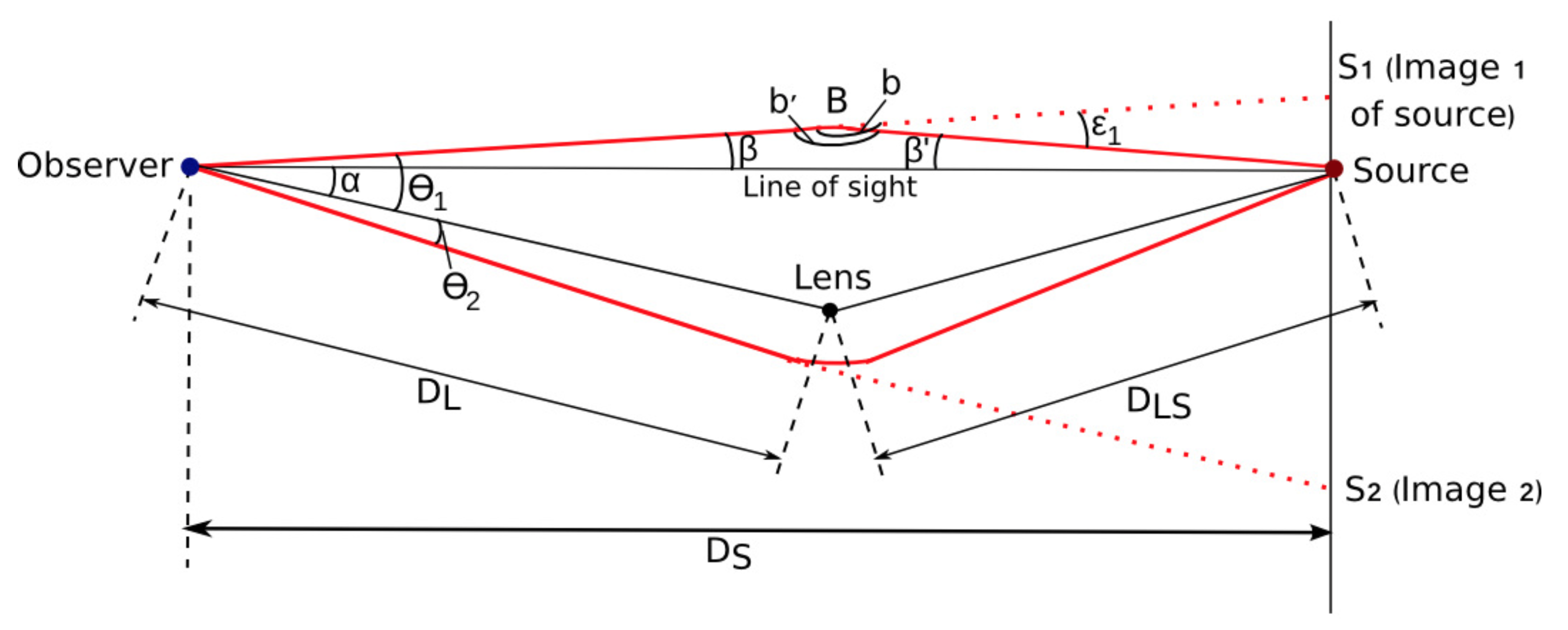
Figure 1 shows a lensing object passing close to the observer's line of sight to a background source star. As Einstein described in General Relativity (G.R.), the light rays from the source passing close to the lens are deflected by its gravity.
The symbols have the following definitions:
DL = distance of the lens from the observer
DS = distance of the source from the observer
DLS = distance of the lens from the source
ML = mass of the lens
α = angular separation of the lens from the observer-source line of sight
θ1,2 = angular separation of images of the source from the center of the lens
ε1,2 = deflection of a light ray passing at radius r from the lens.
The closer the light rays get to the lens, the more they are deflected, according to Einstein's equation:
| $$\epsilon = \frac{4GM_{L}}{rc^{2}}$$ | [1] |
Like any lens, the foreground object creates images of the light source. Consider a light ray leaving the source. It's path is deflected and it reaches the observer, who sees a corresponding image of the source, at an angular separation from the source's true position on the sky.
We will assume that the distances involved are sufficiently large that standard geometric small angle approximations are valid.
From Fig. 1, we observe the following relationships:
| $$\theta_{1} = \alpha + \beta$$ | [2] |
| $$\beta + \beta^{\prime} + b^{\prime} = 180^{\circ}$$ | [3] |
| $$\epsilon_{1} = \beta + \beta^{\prime}$$ | [4] |
| $$\beta^{\prime} = \beta \left( \frac{D_{L}}{D_{LS}} \right)$$ | [5] |
Combining these observations, we can derive an expression for the angular displacement of the image in terms of the G.R. deflection of light:
$$\epsilon_{1} = \beta + \beta \left( \frac{D_{L}}{D_{LS}} \right) = \beta \left( 1 + \frac{D_{L}}{D_{LS}} \right)$$For convenience, we define $$\mu = 1 + D_{L}/D_{LS},$$ giving:
| $$\theta_{1} = \alpha + \frac{\epsilon_{1}}{\mu}$$ | [6] |
| $$\epsilon_{1} = \frac{4GM_{L}}{\theta_{1}D_{L}c^{2}}$$ | [7] |
By substituting [7] into [6], we derive the gravitational lens equation:
| $$\theta_{1} = \alpha + \frac{4GM_{L}}{\mu\theta_{1}D_{L}c^{2}}$$ | |
| $$\mu\theta_{1}^{2}D_{L}c^{2} = \alpha\mu\theta_{1}D_{L}c^{2} + 4GM_{L}$$ | |
| $$\theta_{1}^{2} - \alpha\theta_{1} - \frac{4GM_{L}}{\mu D_{L}c^{2}} = 0$$ | [8] |
Notice how all of the constants are clustered in the last term on the left of eqn. [8]. This term depends on fundamental constants plus the characteristics of the lensing system - ML, DL. So this term describes a characteristic angular radius of the system: it is the angular Einstein radius, θ0:
| $$\theta_{0} = \sqrt{ \frac{4GM_{L}}{\mu D_{L} c^{2}}}.$$ | [9] |
The lens equation can then be written as a quadratic function:
| $$\theta_{1}^{2} - \alpha\theta_{1} - \theta_{0}^{2} = 0$$ | [10] |
...and quadratic functions can be solved to find two roots using the standard mathematical formula:
| $$x = \frac{-B\pm\sqrt{B^{2}-4AC}}{2A}$$ |
where A, B, C are the coefficients of the quadratic equation, in this case A=1, B=-α, C=-θ02. So we solve the lens equation:
| $$\theta_{1} = \frac{+\alpha+\sqrt{\alpha^{2}+4\theta_{0}^{2}}}{2} = \frac{1}{2}\alpha + \left[ \left( \frac{1}{2}\alpha \right)^{2} + \theta_{0}^{2}\right]^{\frac{1}{2}}$$ | [11] |
and similarly:
| $$\theta_{2} = -\frac{1}{2}\alpha + \left[ \left( \frac{1}{2}\alpha \right)^{2} + \theta_{0}^{2} \right]^{\frac{1}{2}}$$ | [11] |
From this, we understand that the observer always see two images of the source created during a lensing event by a single, point lensing body and can predict their positions. The only exception to this occurs if the alignment of the lens along the line of sight to the source is perfect = that is, α = 0. From Eqn. 10, we see that both images then have the same angular separation. In this special case, the image of the source that the observer sees is a perfect ring at the Einstein radius. In all other cases, the images form arcs.
It's important to remember that there is no change in the surface brightness of the source during a lensing event - the light is simply redistributed, and always conserved. As a result, the observer receives more flux from the source, which appears to brighten during the lensing event, even while the source itself remains at constant brightness. As the lens moves away from the observer's line of sight to the source, the latter appears to gradually return to its normal brightness.
We now shift our perspective, and consider the same lensing event from the observer's point of view, shown in Fig. 2. In this lens-centric geometry, we define:
r0 = separation of the source from the lens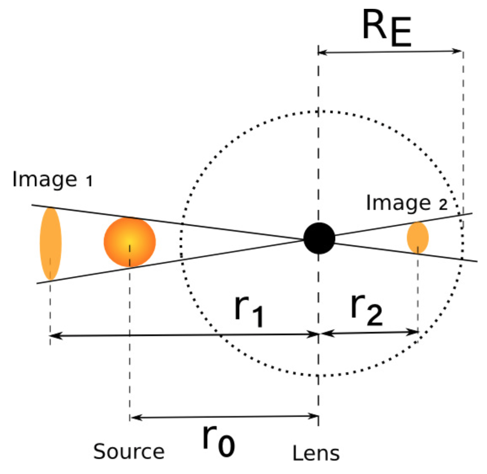
We can re-write the lens equation and its solutions in terms of radial distances from the lens projected on sky:
| $$r^{2} - r_{0}r - R_{E}^{2} = 0,$$ | [12] |
where, to use the commonly-used notation of Paczyński (1986) and others,
| $$R_{E}^{2} = \frac{4GM_{L}D}{c^{2}},$$ | $$D = \frac{D_{L}D_{LS}}{D_{S}}.$$ | [13] |
The solutions of this, i.e. the projected locations of the images, are then:
| $$r_{1,2} = \frac{r_{0}\pm(r_{0}^{2}+4R_{E}^{2})^{\frac{1}{2}}}{2}.$$ | [14] |